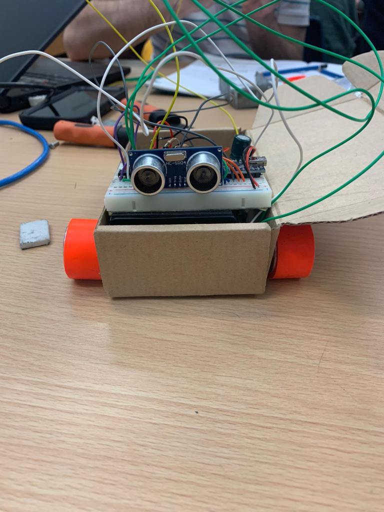
We had recievend the wheels and motors from the supplier over the weekend and we were very interested in testing the speed of the motors. I soldered legths of wire to the motors and then Ben attached the rims and tyres to the motors. Billy was still working on the colour sensor as it was broving to be difficult to get working. I had the idea to use the box that the parts arrived in to build a very basic chassis. I then conneced the motors directly to the 9V battery. This allowed us to visualize the speed of the robot. We were very impressed with the speed of it.
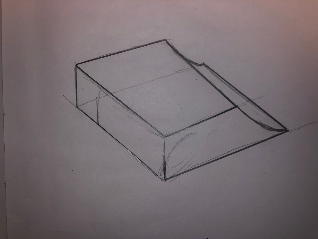
After this testing, we focused on finalizing the design of the chassis. I was planning on buildig it over the weekend and have it completed for week 7. The plan was to biuild the chassis open topped with a floor pan with cutouts for the wheels.
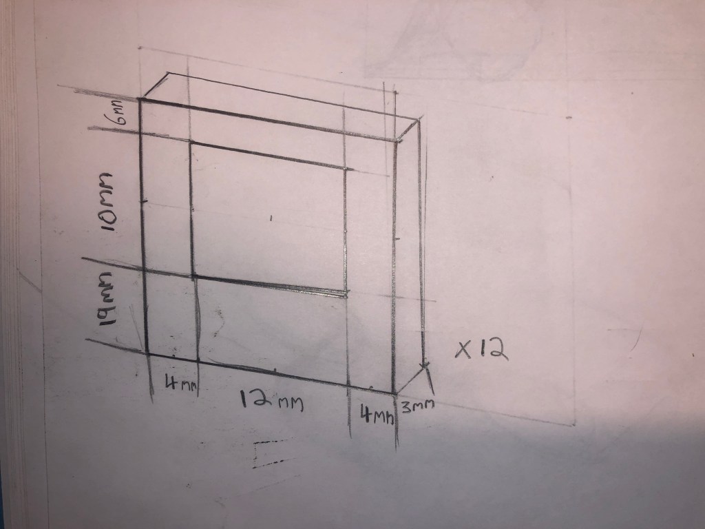
We knew we would need something to mount the motors to the chassis. I thought about how i could builld something from the materials available at home but nothing seemed like an easy option. We then decided to have plasic holders made up in inkscape. I designed the required shape on paper and gave the plans to Ben to draw in inkscape. This would be a much easier and neater way to mount the motors.
I took the components home following the class as I was planning on building the frame over the weekend however the next day the taoiseach announced all colleges were closing. Therefor, i have not built the frame yet.
For week 6, our main objective was to wire and code the TCRT5000 colour sensor. The puropse of this was to tetect the white perimeter of the robosumo ring. Billy focused on wiring and coding the colour sensor while Myself and Ben planned the design of the chassis for the final compitition.
We had made the decisoion to opt for 4 motors and 4 wheels which would give is unrivaled traction, making pushing our opponents out of the ring easy. We decided having protection over the side of the body would prevent a robot beig able to get under our wheels. We knew we would be fitting a ramp to the front to lift the other robot up and push them from the ring.
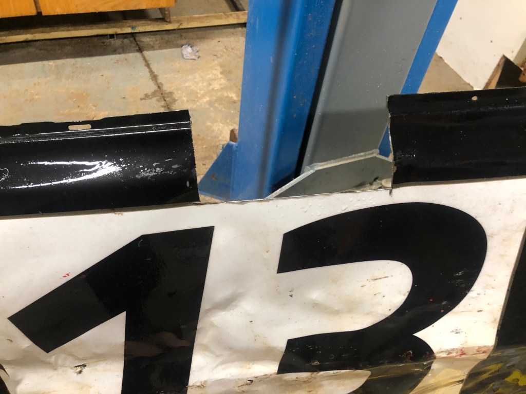
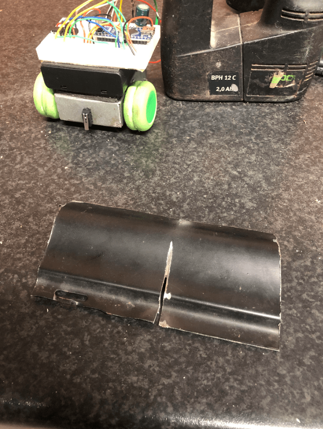
Over the weekend before the tip the can challenge, I built a front bumper for the robot out of scrap steel that started out as the door off my racecar. This was easy enough with the only difficulty being that i had to grind the metal down to make it thinner. this was so that the switch would be closed when the robot touched the can. I fitted the bumper to the robot and positioned it properly. At this point our robot was ready for action.
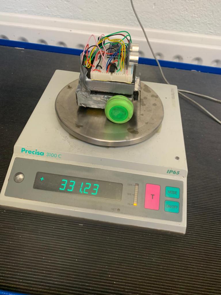
On Wednesday, We were the first team to compete the challenge after verifying our weight and size with a time of 20 seconds. We were happy that we had completed it however we knew we could do better.
We realized the RH motor was spinning faster than the LH motor so we slowed it down via pulse width modulation so that it traveled straighter. After this, our time dropped significantly but other teams had got much faster times. I decided the easiest way was to increase the wheel diameter, gearing up the robot. Given the limited resources, we wrapped folded paper around the wheel and wrapped that in tape.
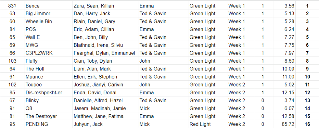
After doing this, another competitor gave us the old wheels off his which were bigger. This helped our robot travel faster but the wheels didn’t have sufficient grip to press the switch so we failed the first attempt with the new wheels. We solved this by using a section of an inner tube to increase traction. We had a significant improvement but we realized other teams were using 9V power so Ben left to buy a 9V battery. We kept the arduino and sensors running off 6V power so that we would not have to re wire the whole system. We added the 9V power to the quad half H bridge chip in order to power the motors. This sped up the robot greatly and significantly dropped our completion time.We were hoping for better results however our final result was acceptable. If we had jumped to 9V power sooner, we feel we could’ve gained a few positions. We ended up with a time of 7.27 seconds which gave us a final ranking of 5th place. Unfortunatly we dont have a video of the best attempt.
When I returned home for the weekend, I had to find suitable wheels to use for the robot and construct the robot frame and assemble the robot for final testing.
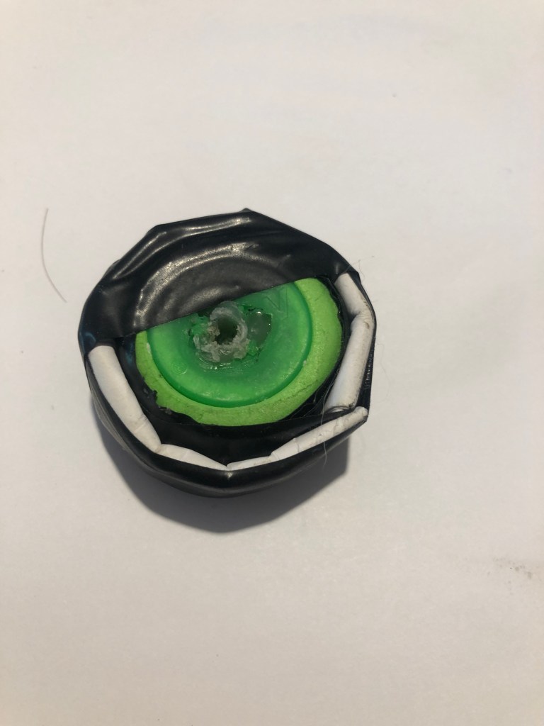
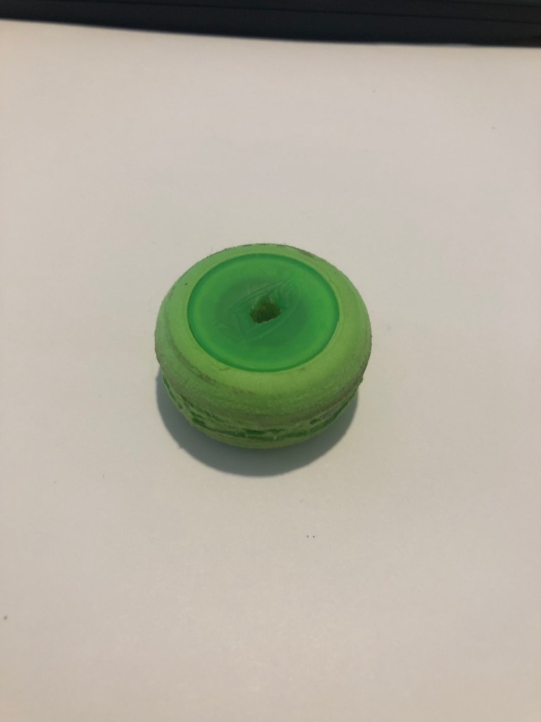
I decided to finalize the wheels first as the robot would have to be designed to fit around these. We had agreed to use wheels which matched the diameter of the wheels we were planning on ordering so that we could settle on an appropriate gear ratio for our final competition. We needed wheels with a 35 mm diameter so i looked through old model cars in the spare room and attic however i didn’t find any. However I found foam and plastic discs which matched the required diameter. I had to fill the centers with epoxy resin, attach 2 discs together and then cut a groove allowing the motors to attach to the wheels.
I then began on the frame construction by measuring the necessary dimensions. I opted for a frame which was 55 mm wide, 20 mm high. The length would be finalized later in order to make the robot as short as possible. This was the minimum size which allowed me to fit the motors, wheels and switch while allowing sufficient space for wiring to be routed through. Once i settled on the dimensions, I marked the required lines on 1 mm galvanized plate and cut them with the angle grinder. I drilled the nescessary holes to allow the motors and switch to be fitted. The motors were held in situ with 4 small self tapper screws. I was planning on securing the switch with epoxy however the tightness of the hole provided sufficient support.
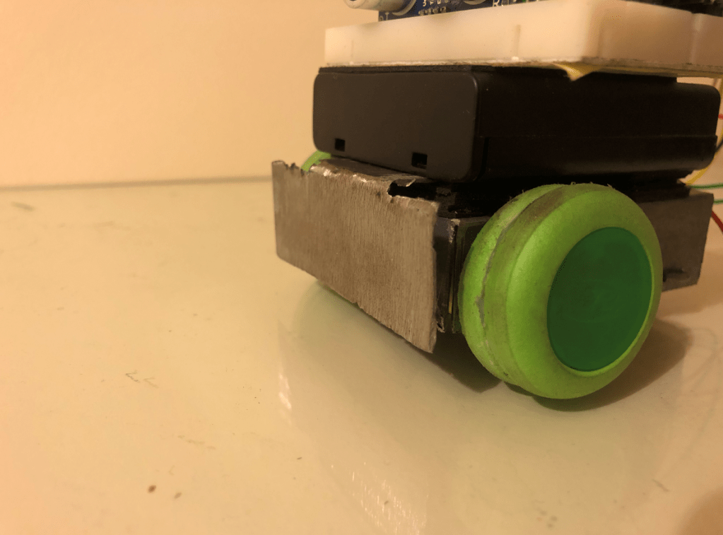
With the motors mounted, i focused on building a small rear axle to support the rear of the robot. I found a metal coat hangar and a small model car wheel which could be used. I drilled two holes at the rear of the chassis to support the axle and a slot in the rear of the body to clear the rear wheel. I passed the axle through the holes on the chassis and the center of the wheel. I then secured the axle by bending both ends over. When the wheels were pushed on, the rolling chassis was complete. I then mounted the battery pack over the chassis with double sided tape and mounted the breadboard to that, with the rangefinder mounted centrally, facing forward. Once all the components were mounted, I routed the motor and switch wires through the chassis and connected them to the arduino.
At this point I had to test the robot as it was the first time it was able to move. Unfortunately the range finder was not working properly for an unknown reason however I did not have the time to investigate the issue at that point but i knew we would have time to solve the problem in the class on Wednesday
In class, I showed the robot to Ben and Billy and explained that the rangefinder was not behaving properly. Luckily, all that was needed was for the coding to be reloaded onto the arduino. At this point, we had a fully functional robot and all pressure was off for this week because of how well we had worked together. We tested the robot with the can and we were confident going into week 5 as our robot was already proven.
What we noticed was it was a bit unreliable hitting the reverse switch so i thought it would be a good idea to add a ‘bumper’ to it so that it would reverse more reliably when it had tipped the can. We also finalised our decision on the wheels and motors for the final build and placed the order online as we wanted the parts as soon as possible so we could progress as quickly as we had up to this point.
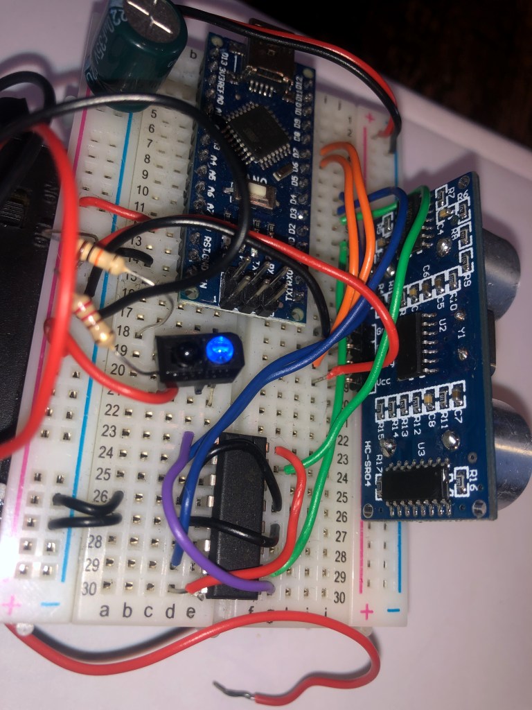
For the third week of our robosumo project, our main objective was to wire and program the HC-SR04 ultrasonic rangefinder. The HC-SR04 works in a similar manner to radar developed during WW2 by emitting an ultrasonic sound wave from its speaker and listening for the reflected signal. The Rangefinder can be used to determine the distance between the robot and the target by dividing by the speed of sound. However, we did not require this feature for tip the can, simply needing a binary yes or no answer on whether the can was in sight.
The use of the rangefinder was vital to the completion of the tip the can challenge as it allowed the robot to find the can and steer towards it. I was given the task of installing the rangefinder to the breadboard and connecting it to the arduino. This was surprisingly simple as it only required a 5V input and ground. The echo and trigger pins had to be connected to digital pins on the arduino with the trigger wire being programmed as an output. We discussed what we would need the coding to do and settled on the following.
When the can was not in direct line of sight for the robot, it would reverse one wheel, turning the robot on the spot until the can was seen. When the can was in sight, the robot would drive staight towards it until the switch was pressed. When pressed, the robot would reverse for one second then stay at rest for 10 seconds, validating the challenge.
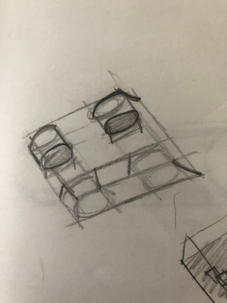
While Billy focused on the coding, Ben and I began discussing the chassis design. We agreed to design something simple yet effective which did not waste any excess space or materials. Due to the fact that we would not be competing with another robot, we did not need to incorporate any attack or defense measures into our initial design. While other teams were going to be building their frames from plastic sheets, we agreed to use steel plate instead. This was because I have years of race car fabrication experience and constructing it out of waste steel would provide a simple, efficient and fast for us. We settled for a design of a base frame which would house the wheels, motors and switch with the battery pack and breadboard stacked above this. The final design was left to me to be tweaked given any space and material restraints.
For the second week of our RoboSumo project, we received information on how to control the motors via the SN754410NE 4 Channel Half-H Bridge Driver. We learned that the driver essentially functions as 4 relays combined, with the ability to provide a much higher current output than is safe for the arduino to supply. Additionally we learned the required coding on the arduino to power the motors both forward and reverse. Of the two outputs to the motors, one had to be live with an ‘on’ signal while the other had to be negative with an ‘off’ signal from the arduino. If either both outputs were ‘on’ or ‘off’ the motor would not turn while swapping the polarity on the motor would cause it to reverse.
Billy and Ben focused on the coding while I set up the wiring and soldering on the breadboard and on the motors. We soon had a simple proof of concept which showed the motors turning, representing the robot driving, reversing and turning.
Once we were satisfied with this, we agreed to proceed and add the switch which allowed the robot to sense the can for the tip the can challenge and to reverse as required. Wiring this was simple as it only required a resistor and the switch to be added. Additionally, the coding was straightforward as only one extra input was required and when a signal was sensed, the motors were reversed for a short amount of time then turned off.
This is my first post on my RoboSumo blog. This will cover the beginnings of our project. Mt team consists of Ben Nel, Billy Hamilton and myself. We agreed to team up again as we have a proven track record working on projects together this year.
Once we had been briefed in the lecture, our first challenge was to wire and code an LED to flash, using the Arduino. This was completed with relative ease once we understood the coding system.
Once this was completed, we then had to configure a second LED and code both to be able to display our team number in Binary. This was much more challenging as none of us had an understanding of binary. Once we found our team number to be 1000001, we then had to determine the sequence needed for the lecturers program to recognize the code. once we had this, it was relatively easy to modify our coding. Once completed, we tested our coding off a laptop to check the sequence. Our code was perfect from the get go and we were the first team to complete this challenge. Hopefully a sign of future victories!
This is John Fernihough’s blog following the progress of the robot build for the 2020 Robosumo challenge for DT066A. More updates to follow as we progress further. Stay tuned!